Streamline Your Manufacture Process
Using CAD drawings in CAD/CAM softwares is becoming more common each day. They help with quickly getting the dimensions of the tool to the machine. The drawings are also useful for understanding what the specific tool looks like.
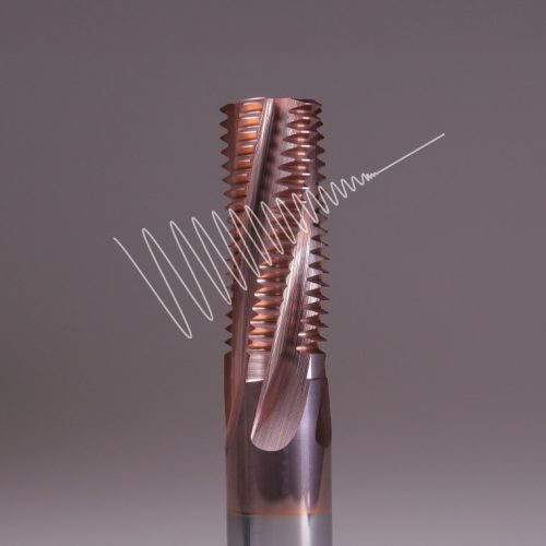
SmiCut has made simplified 3D CAD files of the complete program of Solid Carbide Thread Mills. They are made accessible as a STEP file, an ISO standard exchange format that can be opened in many different CAD programs.
You can download the CAD Drawings from smicut.store
How to download
- Go to our online store and search for the tool you want the CAD drawing of.
- When you find the tool in the list, press the part number.
- On this page you will find the link to download the CAD Drawing.

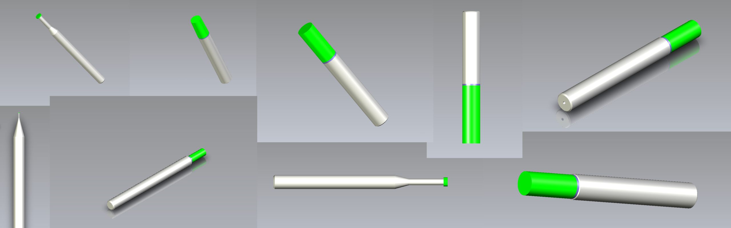
Information about the 3D CAD Drawings
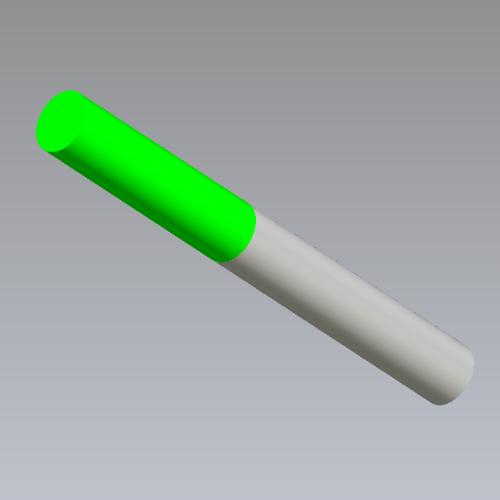
- The green area of the drawing is the cutting part of the tool. This usually corresponds to the cutting length measure ( l )
- The grey area is the non cutting part.
- Some tools has a purple area. That is a cutting part of the tool that can be used if you want the tool to deburr more.
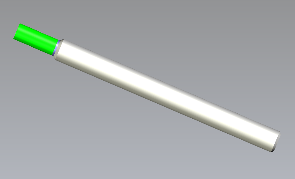
NB0403C7_0.7ISO_AC as a simplified 3D CAD Drawing
Links
SmiCut Online Store
Thread Milling Tools