Streamline Your Manufacture Process
The use of CAD drawings in CAD/CAM software is increasingly common. These drawings facilitate the rapid transfer of tool dimensions to machines and enable the simulation of machining operations. The drawings are also useful for understanding what the specific tool looks like.
SmiCut offers simplified 3D CAD files for our program of FourCut threading tools. These files are available as STEP files, an ISO-standard exchange format compatible with various CAD programs.
You can download the CAD Drawings from smicut.store
How to download
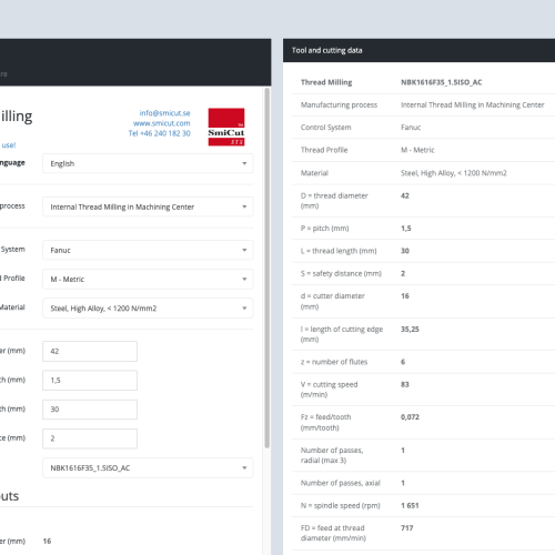
- Visit our online store and search for the tool for which you need the CAD drawing.
- When you find the tool in the list, press the part number.
- On this page you will find the link to download the CAD Drawing.
Information about the FourCut Drawings
To get the correct drawings for the tool simulation it is important you take in consideration the following information.
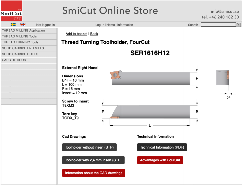
Holders
- There are two versions of each holder to download. One with a 2,4 mm thick FourCut insert where the cutting edge is in the middle (Y=1,2) and one holder without the insert.
- If the insert you are using has a Y measurement of 1,2 mm, the simulation will be accurate from the beginning.
- If the insert has a different Y measurement, do the following to get the correct tool simulation.
- Download the STEP file of the holder without the insert.
- Download the STEP file of the insert you are using.
- Combine the holder with the insert.
- If you prefer not to combine the holder and insert, you can manually adjust the Y measurement in the machine. The correct Y value for the insert can be found in the Online Store and Catalogue.

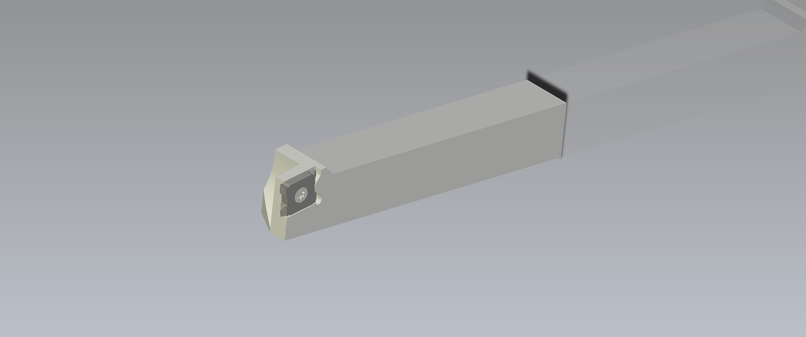
SER1616H12 FourCut holder with a 2,4 mm insert.
Inserts
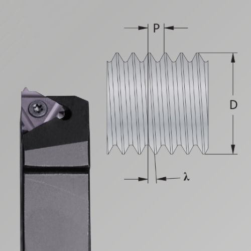
- Have in mind that the inserts are simplified drawings. They dont´t show the actual thread profile.
- The inserts has the correct Y measurement. That is the important measurement to get the tool simulation correct.
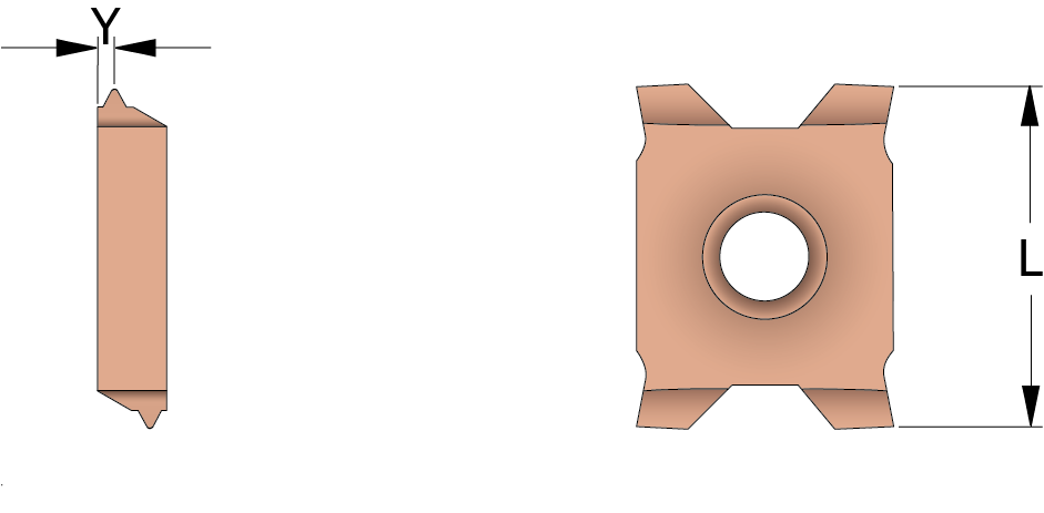
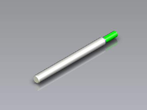
The simplified 3D CAD drawings of the FourCut inserts has the correct Y measurement so that the tool simulation will work as intended.
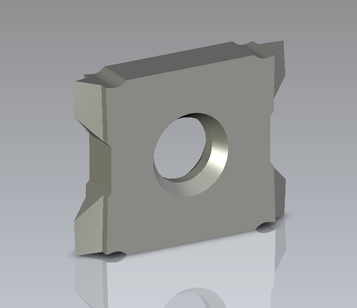
12E_1.25ISO_HC as a simplified 3D CAD drawing.